 Another follow on to a few earlier posts today. I previously documented flashing my Arilux/Magic home LED controllers with Tasmota and also did a comparison review of the Arilux vs the H801 controller. Today’s post is a quick update on a few gotchas I found when flashing the H801 with Tasmota compared to my previous effort of flashing the Arilux/Magic Home device.
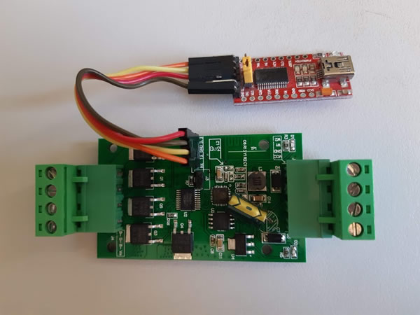
Firstly the process to flash the device is mostly the same as I previously did with the Magic Home controller, only adding the programming header was much easier in this instance. One thing to note is that the PCB is labelled the opposite way to other similar devices I have seen. So instead of connecting TX to RX and RX to TX you connect TX to TX and RX to RX. Fortunately VCC and GND are printed correctly so once your FTDI adaptor it is all connected up like below and a jumper across the 2 pin header it was a simple process of sending the tasmota.bin file to the device with Tasmotizer like I previously documented here. Once flashed don’t forget to remove the jumper from the 2 pin header.
After I flash a new device with Tasmota I generally make use of the serial console and my still connected FTDI adaptor to send my Wifi details to the device via Termite. However, my first try of this looked like it was not working as I received just junk back on the termite window and not the Tasmota console output I normally would expect to see. This gotcha is explained on the Tasmota page for the H801 under “first boot”. It seems the H801 is using a different GPIO port for serial TX than most other boards so the output was not shown, fortunately the RX GPIO port is the same and the device did read my commands when I sent my Wifi details to it and it was ready for me to go to the Tasmota GUI as I normally do to continue set up.
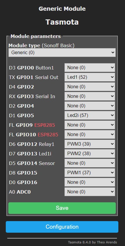
The next issue is the Tasmota page says to send a “Module 20” command to set the device up as a H801 and this worked ok and configured Tasmota with all of the H801’s supported features. Unfortunately for me I was using the device with RGB LED strips and not RGBW or RGBCW strips like the H801 device supports, so some manual configuration is required in my case.
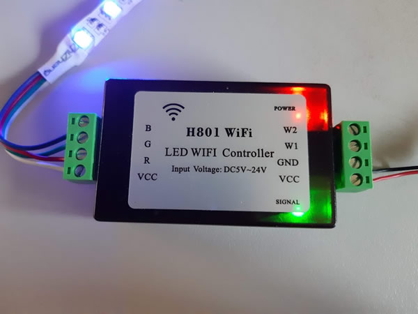
To configure the device for RGB only, configure the module as a generic module with the setting like below. The 3 PWM settings are important here as you are not using the two W1 and W2 outputs on the H801, and are connecting your strip to the VCC R G and B outputs as shown in my working picture above. The 2 LED settings are only for the onboard indicator LEDs that you can leave set to none if not needed.
Wrap up
Once my H801 device was configured like above my RGB strips reacted correctly to selected colour.
A bonus reason for setting up the device manually would be the addition of push button. The 2 pin header that you short for programming is actually just GPIO0 and GND. Connecting a button across here and setting D3 GPIO0 to Button1 will give you a manual push button to turn on or off the LED strip.
As stated at the start of this post, this post is not intended as an extensive guide to program the H801, just the highlights of the differences and pitfalls you may come across when setting up a H801 compared to my previous posts. If this is your first time programming the H801 start with my resources below but also be mindful of the gotchas above.
Resources
Flashing the Arilux / Magic Home Controller with Tasmota
Flashing Tasmota to esp8266 devices the easy way
Tasmota firmware download page
Tasmota’s H801 page
H801 Controller at BangGood