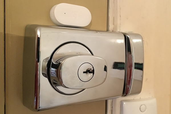
There seems to be a new smart lock on the market every week and while they interest me I do have a few issues with them. Firstly the options where I live (Australia) are a bit limited and are also crazily expensive and secondly I am not sure I want really want to have the lock to my house available on the internet (although I am more likely to be broken into via a brick to the window over someone hacking me). Anyhow, what I really want from a smart lock is knowing that I have not accidentally left it in the unlocked state. So that got me thinking maybe I can cheaply modify my classic Lockwood 001 deadlock to tell me the state it is in.
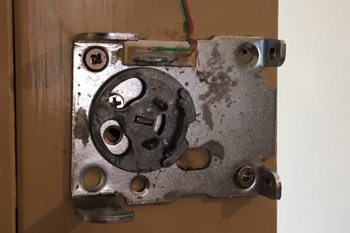
On inspection of my Lockwood 001 lock which would be over 20 years old (it came with the house), I found there was huge amount of travel of the latch when you put it in the unlocked passage mode. It was this mode I want to get status of and there seemed to be a fair bit of room in there where I could mount a magnet and reed switch. So this is what I did using a few cheap parts from banggood.com.
Parts Used
Xiaomi Mijia Smart Door & Window Sensor
Step 1
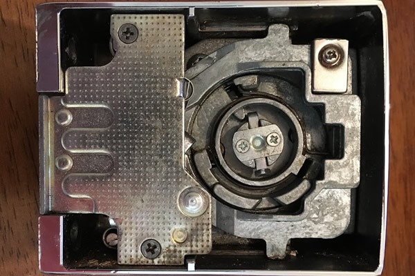
I attached a magnet to the latch (see top right below), the latch alloy is easy to drill and tap, I used a small screw I had lying around. The magnet was a bit too long so I had to cut it down which I achieved on the first go. It was more good luck than good management as the magnets are really brittle (fortunately they come in a pack of 10). I mainly chose the magnet I did as it was only 3mm thick and I thought any thicker may cause issues.
Step 2
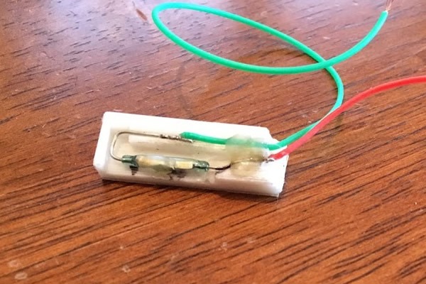
I created a reed switch holder and 3D printed it. The reed switch has some thin and flexible telephone cable soldered to it. I also cut out a bit of the door lock mounting plate for the holder to sit in. It is fastened to the door mostly with some double sided tape and a small bit of hot glue.
Step 3
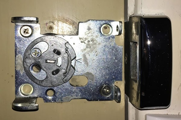
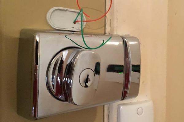
A small channel is cut out of the door wood from under the lock. The cables from the reed switch will pass through this channel up into the Zigbee door and window sensor case via a hole is drilled in the back of the case. The cables are hot glued into place.
Step 4
The Lock is reassembled and has one last final clearance check. I also check the latch in both positions with a multi-meter on the reed switch to confirm the switch is working.
Step 5
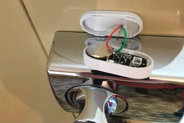
Trim the wires down so they fit in the Zigbee case but there is also still room to solder it and remove it from the door to replace the battery. I chopped off the Zigbee sensors original reed switch and soldered mine to the where the original switch was connected. It may take some jiggling of the wires to get the case closed nicely.
Step 6
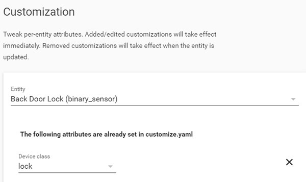
The Final step is connect the Zigbee sensor device to Home Assistant. I use the zigbeetomqtt plugin to connect my Zigbee devices to Home Assistant. However you connect your Zigbee devices in to Home Assistant, there is one thing you need to do in Home Assistant once the entity is discovered and that is go to Configuration and then Customization and find your new entity. Then change the device class to “Lock”. Once that done when you add your new entity to your UI you will see it as a lock and its state.
Wrap Up
I have been using this with Home Assistant for several weeks now and it has not missed a beat. I also have setup an automation to remind me the door is unlocked when I am setting the alarm at the other door. I used Zigbee as it was cheap, small and good on battery life, but you could also use the same principal with any small battery powered reed switch type sensor.
Example of my Home Assistant Lock entity in the lovelace UI