Background
As I slowly add more smart devices to my house I keep finding the need to add some smarts to some of my older stuff. My 10 year old Samsung TV is one such device that occasionally doesn’t turn off when you hit the button on the front, so if I could automate an off command via an IR blaster when I leave the house or go to bed I would save a bit of power.
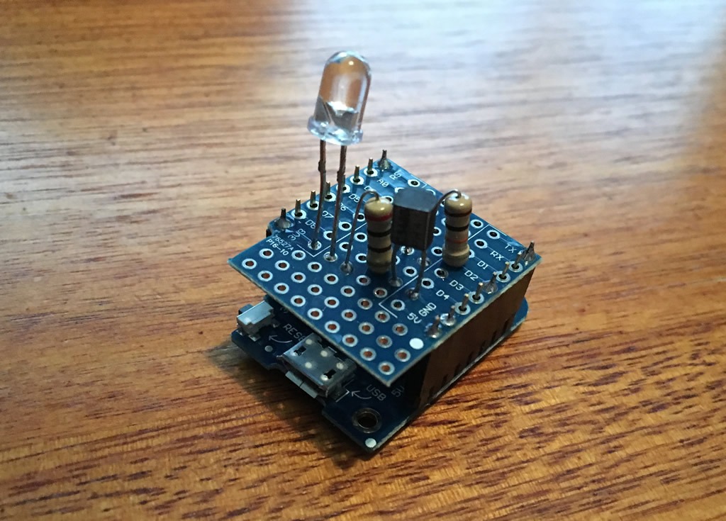
I have several ESP8266 devices around my house used for various sensors and I generally use the Wemos D1 Mini as its easy to work with and fairly cheap. So a D1 Mini, A D1 Mini proto-board with a few components are the hardware behind this project.
On the software side of things I generally use Tasmota firmware but this time I thought I would try out ESP Easy to see what it was like. It was pretty easy to set up and ran for several months before I decided to convert this device to Tasmota. There is nothing wrong with ESP Easy, I just decided to have all my devices on the one firmware. I am documenting the below from what I remembered I did a few months back (so I don’t forget if I ever decide to revert this unit back to ESPEasy).
Hardware Setup
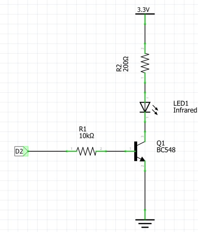
Hardware wise I am using a IR led that I scavenged from an old VCR remote. This is driven by a small BC548 transistor via a couple of resistors to pin D2 of the Wemos D1 Mini as shown in the schematic below. The values here don’t need to be too exact and any similar NPN transistor should do the job.
Getting the right codes
So you really want to know that you are turning the telly off and not just power toggling it or you may end up turning it on when you don’t want it on. My Samsung remote only has a power toggle button but a few years back when setting up my harmony remote I tried setting up several different models of Samsung TV until I found a power off and power on command that my TV supported. These off and on buttons have been on my remote for a while so that was step one out of the way.
Step 2 was finding out what the codes of both buttons were, fortunately my kitchen LED strip is an ESP8266 based device running Tasmota (that will be another post one day). This strip controller also has an IR receiver, so I pointed my Harmony remote at the receiver while watching the console section of the Tasmota admin interface and the received codes were displayed like below.
off press ={“IrReceived”:{“Protocol”:”SAMSUNG”,”Bits”:32,”Data”:”E0E019E6″}}
on press ={“IrReceived”:{“Protocol”:”SAMSUNG”,”Bits”:32,”Data”:”E0E09966″}}
Other alternatives for finding your codes is one of several online databases or forums of IR codes, I haven’t used them so you will have to hunt them down yourself.
Flashing the Wemos D1 Mini with ESP Easy
The flashing instructions on the ESP Easy site may look daunting but with the Wemos device it could not get any easier. Simply plug the USB into your PC and it will come up as an extra serial port, you will then use this port to flash a bin file to using FlashESP8266.exe that will come in the zip file you can download from the ESP Easy releases page.
Jump to the section titled”Flashing the nodeMCU / WeMOS D1 mini” on the ESP Easy site for full details on this.
Once flashed reboot the device and connect to it with your smart phone to connect it to your network. There is more details on this at the bottom of the ESP Easy site section titled “Where to go from here”
ESP Easy Setup
Once you figure out the ip address of your Wemos d1 Mini (I generally look up the attached devices page of my router if I forgot to note it during setup) go to the ip address in your browser to set up it up.
Config Page
This one is self explanatory, this is where your wifi details will be and here you can add a unit name so you know what it is on your network (mine is called IR). You probably should add an admin password as well to secure your esp-easy admin pages.
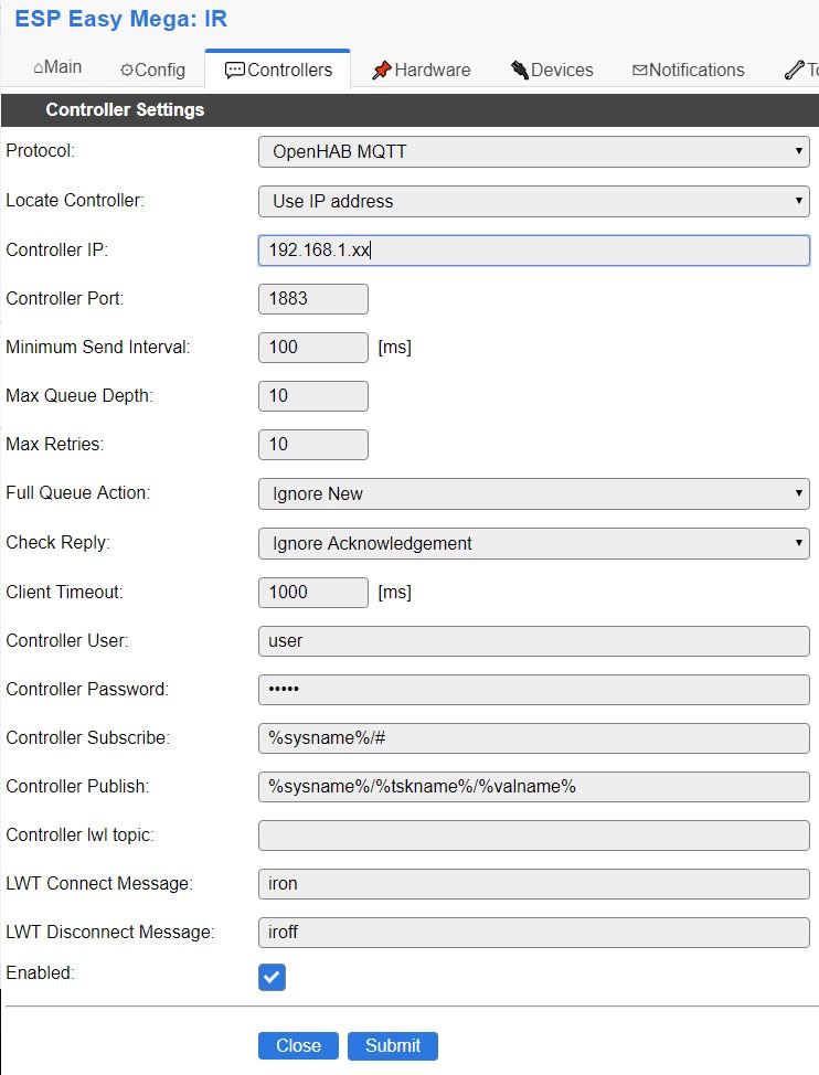
Controllers Page
As we will be communicating to the blaster via mqtt you will need a mqtt server setup on home assistant installation. On ESP Easy Controllers page Select “Openhab MQTT” and fill out the details of your mqtt server. The ip address, user and pass should be enough with the rest left as default. Ignore the fact it says “openhab” and not “home assistant” as both mqtt setups should do the same job.
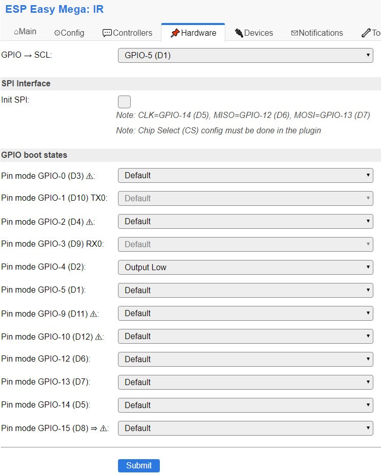
Hardware Page
I only changed Pin mode GPIO-4 (D2): to “Output Low” here. This is the pin my IR led is connected to, if yours is different adjust accordingly.
Devices Page
Select IR communication and the pin your IR led is on (GPIO-4 D2 in my example)
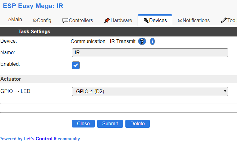
The rest of the pages can be left as default.
Testing
Before we get carried away setting it up in Home Assistant lets test that the device is working directly. You can do this by sending a http request via your browser in the format of below.
http://your.ip.address/control?cmd=IRSEND,encoding,value,bitlenght
In my case I sent the Samsung ON command using my local url below and the telly soon fired up so now I know I can move on to the next step (although you could just add these links to the home screen on your phone if you just wanted to control your telly from your phone only)
http://192.168.1.34/control?cmd=IRSEND,samsung,e0e09966,32
Home Assistant Configuration
Add the below mqtt platform under you switch section of your configuration.yaml. Check you config and reboot. A switch.tv should come up under your list of entities with the friendly name of TV.
switch:
  - platform: mqtt
    name: "TV"
    command_topic: "IR/cmd"
    payload_on: "irsend,samsung,e0e09966,32"
    payload_off: "irsend,samsung,e0e019e6,32"
Wrap Up
After a reboot of Home Assistant you should now have an entity called switch.tv. You can use this in in an automation and display it in your frontend like below.
![]()
I ended up putting the IR Led on short wires and tucked it out under the leg of my amp pointing at the TV so it is barely visible, the Di Mini hangs behind the TV cabinet in an old project box I had lying around.
Update April 2020
I have since added IR control to Home Assistant with an off the shelf solution. If the DIY route is not your thing, check out what I did here.