One of the fanciest things with home automation is to install motorized blinds. Unfortunately it is also one of the most expensive bits of automation kit you can buy, that is unless you take a DIY approach to it.When I started to look around for motorize roller blinds I kept hitting results of “you cannot retrofit existing blinds” followed by here is a link to our pricey new motorized blinds. After this I changed my search and found a range of tubular motors across ebay and banggood.com that had very little info about them but looked like they would fit the bill.
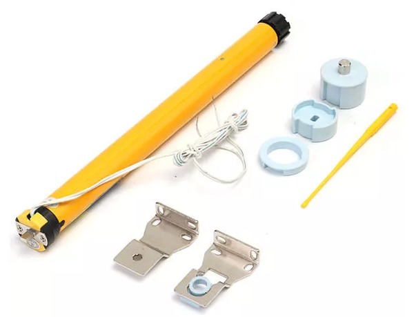
The motor I ended up purchasing was a 12 volt motor marked A-OK AM25-1/30-D (shown above). It is often listed as a 25mm motor but that is the size of motor itself. In order to use this motor with your blinds you need blinds with a 38mm tube, fortunately 3 of the 4 blinds had this common size tube and I could also purchase a new tube from ebay for the 4th easily.
The motor comes with very little info, just a sheet with a few diagrams all written in Chinese. Fortunately it was not hard to figure out how to use this motor. There are two wires coming from one end of the motor that when you add 12 volts on it one way the motor spins clockwise until it hits it limit. reverse the polarity and the motor will spin counter-clockwise until it hits the other limit. On the end there are two small adjustments that you use to set the limits once you have the blind installed.
Knowing how the motor operated I decided to create my own controller using an esp8266 with two relays controlling the 12 volt supply to the motor. Although there are mains powered motors available, choosing the 12 volt DC motor allows the whole controller and motor assemble to run off a 12 volt power pack which was easier to run cables to and will keep the Australian authorities happier, as they often frown upon DIY mains powered devices. I also had plenty of 12 volt plug packs lying around and the hardware required for my controller is pretty cheap. I will be flashing the ESP8266 with the Tasmota firmware and controlling the blinds via Home Assistant.
Blind Motor Install
The roller blinds I installed the motor in are the type that have a spring in them that when you gave them a tug they will release and roll up. You will loose the tug to pull up functionality by installing the motor but at least you can roll up the blinds from anywhere in the world now. What I did was remove the spring and replace it with the motor, the spring end will have a flat lug that holds the blind into the bracket while the non spring end had a round rod that allows that end to spin freely. Below are pics of the blind tube with the spring removed and the motor being inserted.

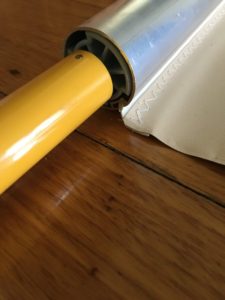
Once inserted ensure the ring at cable end fits snugly between the roller tube and the adjustment collar. This ring has a cutout that engages with a sensor in the motor to tell the motor when to stop once it has reached its limit.
Controller Hardware Setup
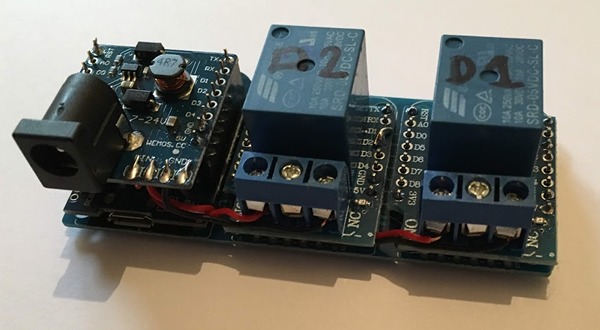
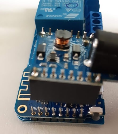
The ESP8266 I am using is a Wemos D1 Mini with 2 relays shields on a tripler PCB. I am also using a DC Power Shield that allows me to power my controller from 12 volts. This same 12 volts connects to the relay outputs to sent power to the 12 volt blind motor. One issue with the Wemos relay shield version 1 is that it is pre-configured to connect to pin D1 only, this would be no good in our situation as we need to control both relays individually. A quick modification is needed to convert one of the relays to pin D2. I simply pull the D1 pin up through the PCB and fold and solder it over to D2. Any excess popping out at D1 needs to be trimmed off so it makes no contact (v2 of the relay shield has pads underneath that you can solder and cut to choose the connected pin). Now when you assemble the boards you will have the original relay connected to pin D1 and your modded relay connected to pin d2. When putting the assembly together ensure none of your boards are shorting out on the tripler base below.
Wiring it up
Once your board setup is assembled you will need to link 12v and gnd wires to the relays. I wired 12v to the both relays NO output and GND to both relays NC output. The motor wires connect to the center Common connector of each relay. It is a 50:50 chance you will hook them up the correct way. If the motor doesn’t go up when pushing up, swap the motor wires around.
Optional 3D printed box
I found a nice wemos tripler base box on thingiverse that would suit the above pcb, there was no lid for the box so I did a mod of the guys design and what you see below is the end product of the two parts together. Two wire holes were drilled in the base to line up with the common output of the relays. Links to the stl files are at the end of this post.
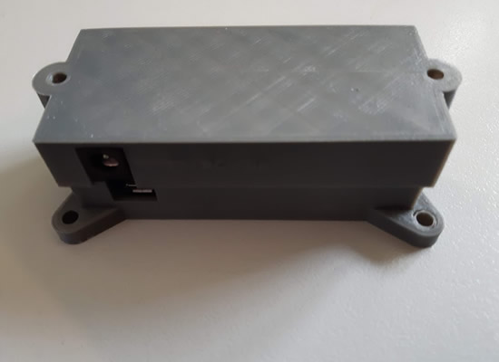
With the exception of the power shield that required a bit more clearance the boards are all soldered together to give the box a low profile as shown below.
Tasmota Setup
Once you have your Wemos D1 mini controller board built you need to flash it with the Tasmota Firmware. If you have not done this before check out my guide here. Once flashed and connected to WiFi the next steps can be all done via the web interface menus or console section.
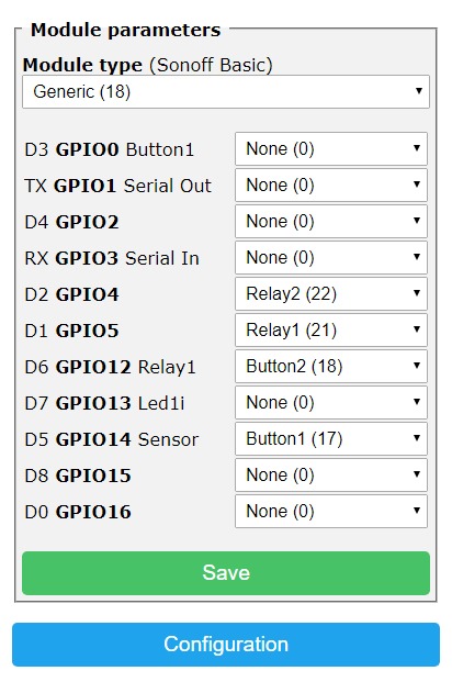
Set up your Wemos D1 Mini like below under Tasmota’s Configure Module menu.
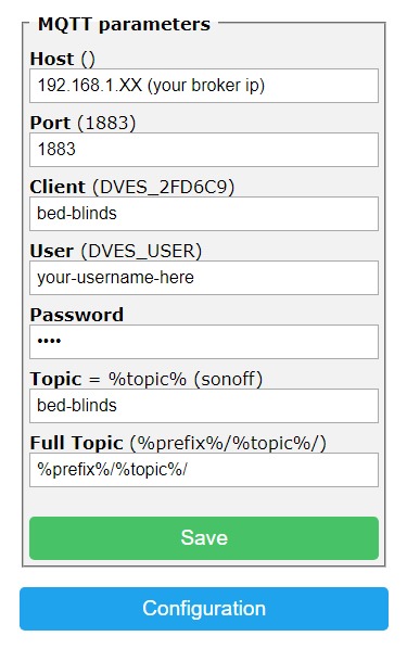
Also don’t forget to add your MQTT broker details under Configure MQTT, also give the device a unique client name.
Tasmota Commands
We need to type a few commands into the Tasmota console to set up relay interlock, relay pulse time, switch mode and 2 Rules.
We will set up the interlock first so both relays are not energized at the same time. Prior to Tasmota 6.5.0 the command was “setoption14 1” but this has been replaced by “Interlock 1” in Tasmota version 6.5.0. If you have done this correctly hitting either of the toggle 1 or toggle 2 buttons on the Tasmota homepage will see the other relay turn off if it is on.
Next is pulsetime, This will tell Tasmota how long to keep the relay energized for. The roller motors will turn off themselves once they get to their limit but there is no point in continuing to send power to them once they are fully open or closed. I found 120 second was plenty of time for my windows so the command I ran was “pulsetime1 120” to set up the first relay followed by “pulsetime2 120” to set up the second. If your windows are larger than mine and relay turns off before the blind stops increase the 120 time. If you have done this correctly hitting either of the toggle 1 or toggle 2 buttons will see the relay turn on for 20 seconds.
Now we will set up the buttons as push buttons with the SwitchMode option. First type “SwitchMode1 3” into the console and hit enter. Do the same again with the command “SwitchMode2 3”
Next we will make 2 rules that will publish a MQTT message each time a relay is fired. We will get the value of this message later in Home Assistant to determine if the controller is in open or closed mode.
First type the following command into the console, adjust the line bed-blinds to suit your needs, hit enter when done.
Rule1 on Power1#state do publish2 stat/bed-blinds/POSITION OPEN endon
Now type “Rule1 1” into the console and hit enter to enable the rule.
Now we will create a second rule to send the OFF mqtt message when relay 2 is powered on.
Rule2 on Power2#state do publish2 stat/bed-blinds/POSITION CLOSED endon
And similar to before type the below to enable rule2.
Rule2 1
Optional push buttons.
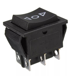
On a few of my blind controllers I have added an up down momentary rocker switch like shown below, you could use a similar switch or two push buttons. I chose to connect these to D5 and D6. Wiring was as simple as running a single GND wire to the center terminal and a wire from each side of the switch to D5 and D6. A single push of the up button energizes the up relay while a second push stops it, resulting in a half open blind. Pushing the down button will energize the down relay and will toggle the blinds direction if it is already in motion.
Home Assistant Configuration
Below is the binary_sensor and cover section of my configuration.yaml. You will need to adjust your topic to suit what you made the topic under “configure MQTT” in Tasmota.
binary_sensor:
  - platform: mqtt
    name: "Bedroom Blinds"
    state_topic: "stat/bed-blinds/POSITION"
    payload_on: "ON"
    payload_off: "OFF"
    qos: 0

cover:
  - platform: template
    covers:
      bedroom_blinds:
        friendly_name: "Bedroom Blinds"
        value_template: "{{ states('binary_sensor.bedroom_blinds')|regex_replace('on','open')|regex_replace('off','closed') }}"
        open_cover:
        - service: mqtt.publish
          data:
            topic: 'cmnd/blinds/power1'
            payload: 'ON'
        - service: mqtt.publish
          data:
            topic: 'stat/bed-blinds/POSITION'
            payload: 'ON'
        close_cover:
        - service: mqtt.publish
          data:
            topic: 'cmnd/bed-blinds/power2'
            payload: 'ON'
        - service: mqtt.publish
          data:
            topic: 'stat/bed-blinds/POSITION'
            payload: 'OFF'
        stop_cover:
        - service: mqtt.publish
          data:
            topic: 'cmnd/bed-blinds/power1'
            payload: 'OFF'
        - service: mqtt.publish
          data:
            topic: 'cmnd/bed-blinds/power2'
            payload: 'OFF'
Automating your Blinds
Now we have the blinds setup in Home Assistant we can create some automations. Below is an example from my automations.yaml file where the Binds open at 7:45 and close just after sunset. I also have a condition that when on a day when it is forecast to be over 29 Degrees C the blinds won’t open(I am pulling the forecast from the DarkSky component here).
# Sunset bed blinds
- id: bed__blinds_close
  alias: Sunset Bed Blinds
  trigger:
    platform: sun
    event: sunset
    offset: '+00:05:00'
  action:
    service: cover.close_cover
    data:
      entity_id: cover.bed_blinds

# bed blinds open 7:45
- id: bed_blinds_open
  alias: Bed Blinds Open
  trigger:
    platform: time
    at: 07:45:00
  condition:
    - condition: numeric_state
      entity_id: 'sensor.dark_sky_daytime_high_temperature_0d'
      below: '29'
  action:
    service: cover.open_cover
    data:
      entity_id: cover.bed_blinds
Wrap up
Spending nearly $70 AU on a motor I knew nothing about was a gamble but it paid off. Also each controller has cost me under 15 bux and I have since converted 4 of my blinds. If I had purchased a new blinds I think I would be into the thousands by now and it is questionable weather these would have be able to connect to my smart home controller. The motors I purchased seem well made and have been opening and closing each day reliably now for several months.
Resources
Flash Tasmota the easy way
Tasmota
Parts Used
Blind Motor
Wemos D1 Mini
DC power Shield
Tripler Base
Relay Shield x 2
Optional up down switch
3D Printed Box