I recently had one of my Arilux LED Controllers die on me, When it came to buying a replacement I found my favourite controller the H801 was out of stock, so I went on to purchase a new model known as the W03 and test that out. Below is my experiences on using it and flashing it with Tasmota.
Overview
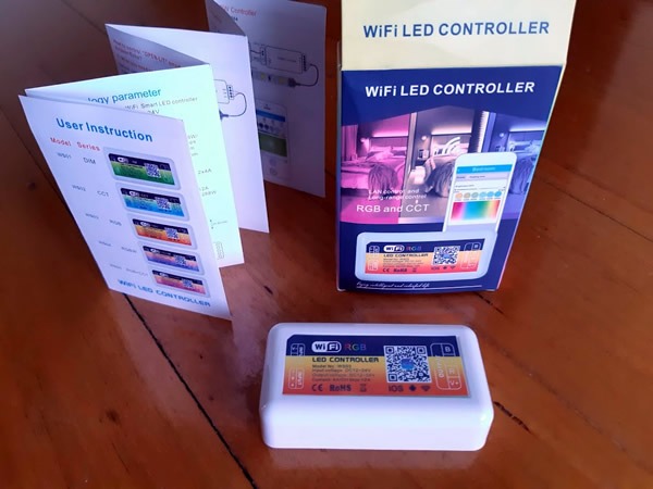
The W03 LED controller is a sub $20 controller used for controlling analog RGB LED strips. Like many other controllers on the market, there is no brand name on the box except for a QR link to a downloadable APK file known as Open Lit. If you search the Android or IOS app stores, you will find this Open Lit app is available to download and is the same as what is shown on the box. I downloaded the APP to check it out, and it seemed pretty awful. You also need to register an account to add the LED controller to the app, as my plan all along was to flash this device with Tasmota I decided to skip testing the default app and crack on into the device. Interestingly, the device did not create its own access point like most of these products do when first powered on.
Opening the LED Controller
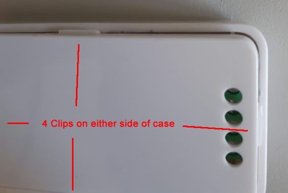
The bottom cover is clipped into place on all 4 sides and a small flat jeweller’s screwdriver is what I used to pry open the cover, which was easier to free the clips from the long side than the shorter side.
Flashing the Device
To flash the device, you are going to need to solder some wires from the controller’s main PCB to a serial programmer. I used some DuPont cables that I have left permanently in the device. These were soldered to the test point pns pins FOR vcc (TP3), tx (TP2), rx (TP1), GPIO2 (TP7) and 2 DuPont cables to GND (TP4) as shown below.

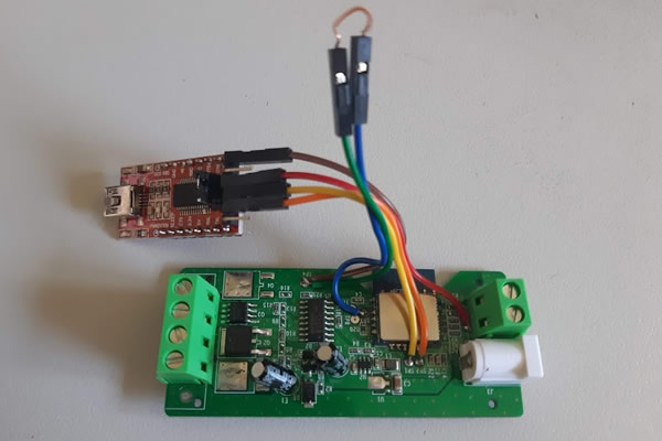
When flashing the device, you will power it from the serial programmer only, and I set my programmer to 3.3v. You will also need to short GPIO2 to GND in order to get the device into programming mode, hence why I added two GND DuPont cables to the device in order to easily jumper the GPIO2 to GND. Don’t forget to remove this jumper once Tasmota is successfully flashed to the device. Some amateur solderers may find this device a bit harder to work with than the H801 LED Controller. My advice is to use a small tip soldering iron to place a small blob on the pads you wish to solder to, and then tin the wire with solder that you are about to join to the pad. A small amount of time is then only needed to join the wire to the pad, also keep the wire short to avoid any bridged joints. When connection the controller to your serial programmer, GND goes to GND (TP4) and VCC goes to VCC (TP3). RX of the programmer needs to connect to the TX (TP2) pin of the controller, and TX goes to RX (TP1).
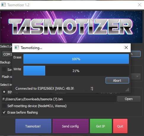
Flashing the device with Tasmota is the done the same way as I have done in a previous post. To recap, we will download Tasmotizer from here and the latest tasmota.bin release from here. Once the serial programmer and your LED controller is connected to your PC, start Tasmotizer select the com port your serial programmer has obtained and then select the release bin file and press Tasmotize! If all went well, then the flashing process should look like below.
Once the flash is complete, you can remove the jumper and reboot the device. Connect to the device by using your smartphone to connect to its AP and update the device with your Home Wi-Fi details, while keeping an eye on the screen once it connects to find out its new IP address. Alternate ways of updating the Wi-Fi info are outlined in my previous Tasmota post. Once you are happy that the device is on your Wi-Fi and you can connect to it from your PC, remove it from your PC and serial programmer and only then should you connect it back to 12v power.
Configuring the LED Controller
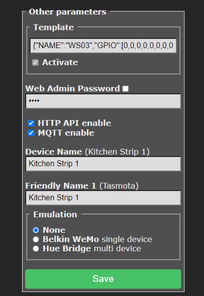
On first boot, the device will be in Tasmota’s default state that will have very little configured. Fortunately, Tasmota added support for templates a while ago, so we can take the configuration that has already been figured out by the community and paste it into our controller without fiddling a lot of settings. The Template for the w03 is located here and basically all we need to do is add this long string below into the other parameters box that can be found under Configuration / Configure Other. Once the string below is inputted, and you click activate and save, the device will reboot and the controls for your LED lights will now be shown under the Main Menu.
{"NAME":"WS03","GPIO":[0,0,0,0,0,0,0,0,418,417,416,0,0,0],"FLAG":0,"BASE":18}
Connect the LED Controller to Home Assistant
If you plan to use your new Tasmota flashed LED controller with Home Assistant, you will need to have a MQTT broker running and working with your Home Assistant install, this post assumes you have set this up already and have your MQTT address, username and password already.
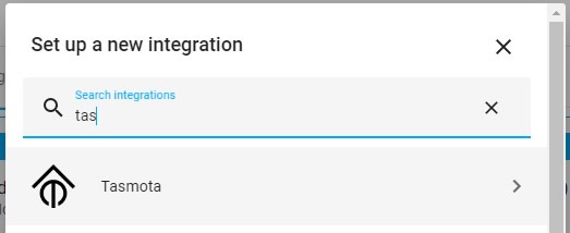
I had previously used MQTT discovery to configure my Tasmota devices in Home assistant, but I now use the Tasmota integration. If this is your first Tasmota Device or the first time using Home Assistant Tasmota Integration, then add Tasmota to your Home Assistant install by going to Configuration, Devices and Services and click Add Integration. Search for Tasmota and click on it.
Now hit submit to add Tasmota to Home Assistant.

No devices may show up just yet, as we need to configure the LED controller to talk to Home Assistant via MQTT.
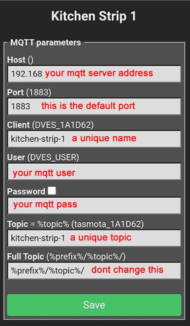
Now over in the Tasmota interface of your LED controller, go to Configuration and then Configure MQTT and configure like below with your settings and hit save.
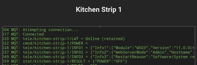
Once the device reboots, go to the Console link on the main menu, and you should see messages indicating that the device is connected to your MQTT broker and some messages from the device to your MQTT broker like below.
To join the LED controller to Home Assistant, we need to run one command on the Tasmota Console page. In the box below the console window, type in the below command and hit enter.
SetOption19 0
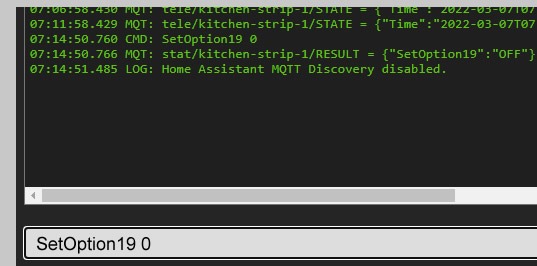
If all went well, your LED Controller should now be available in Home Assistant.
Wrap Up
The w03 is a great little LED controller despite the rubbish firmware it ships with. Fortunately, it was rather easy to reprogram it with Tasmota for local control via Home Assistant. Some people may prefer to work with my previous favourite LED controller, the H801 as it has all its programming pins in a neat row just waiting for a header to be soldered in, while the W03 programming test points do require a fine iron and some experience in soldering small items. I like the fact that there is an option for using either a DC barrel plug or screw terminals for powering the device and the fact there are a few extra GPIOs broken out on test points that could allow for extra add-ons like a temperature sensor to be hacked into the device. Another benefit the H801 has over this device is that the screw terminals on the H801 do unplug, making it easy to take the controller away if you ever need to work on it. When it comes to purchasing a new LED controller in the future it will be a toss up if I go to this W03 model or the H801 as they both have their pros and cons, but I rate them just as good as each other.
If you are after a LED controller that works ok with its own native app and Home Assistant without modifying them, I have found the Magichome based LED controllers that I reviewed here to be a good cheap option.
3D Printed Mount bonus
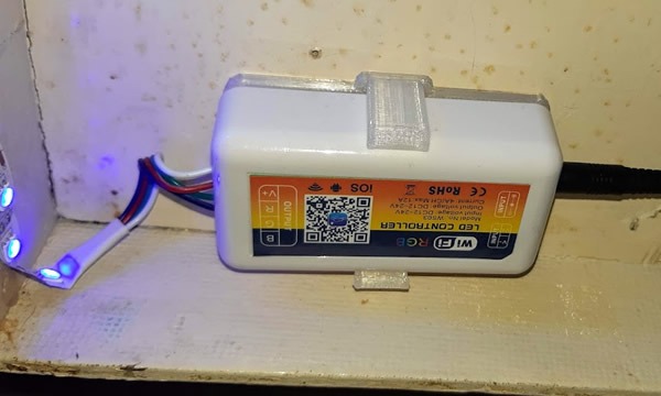
I decided to knock up a 3D printed bracket to hold my LED controller under my kitchen cupboards. If you have a 3D printer, you can download my design at Thingiverse here.
Resources
Flashing Tasmota the easy way
Tasmota Releases
W03 Tasmota Templates
Tasmota Integration page at home-assistant.io
Tasmota’s Home Assistant Docs
W03 LED Controller at Bangoood
W03 LED Controller 3D printed bracket at Thingivese