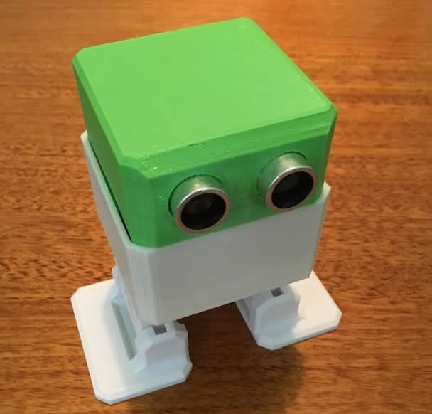
Recently I built my first Otto Robot that you will see in my blog post here. I decided I wanted him to do a bit more than just dance all day long as well as make use of his sensors and buzzer. The first steps are to add a hc-05 bluetooth module and a TTP223 touch sensor to him to bring him closer to the Otto Plus design outlined here.
I will be doing things a bit different this time round and will be using the Otto_v3.ino code from this guy here. My reason for using this version is that this guy has modded the code to work with one touch sensor. I felt that Otto’s tummy was full enough without the two extra sensors that are used in Otto Plus, so one touch sensor in the head to switch between his different modes seems like a perfect solution.
Adding The Touch Sensor
Adding the sensor to his head is rather easy but you will need to solder the 3 wires on if you use the BangGood sensor I linked above.
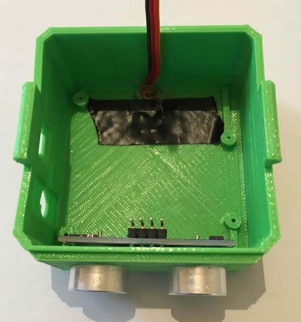
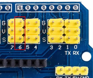
Make sure you tape the sensor down in the thinner part of his head, not only to hold it in place but also to avoid shorting on the pcb above. I also used some hot glue to hold the wires in place. Connect the i/o of the touch sensor to input 6 of Otto’s PCB with GND to G, VCC to V and I/O to S.
This location is different when compared to the original Otto Plus design, whose 3 touch sensors connected to analogue input side of the Nano. If you are using different arduino sketch than the Otto_v3.ino that I am using above than the touch sensor may not register touches to Otto’s nano brain.
Adding the Microphone Board
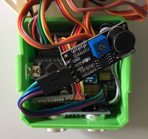 One of the modes of Otto’s new sketch is sound detection. It’s pretty basic and he won’t become the next Siri but clapping or shouting at him should make him behave differently. The mic boards are fairly cheap and easy to hook up. I got this version here and it connects to connector A6 with GND to G, 5v to V and OUT to S as shown on this diagram here.
Adding a Bluetooth Module
The main reason to add Bluetooth to Otto is to control him from an app. The original Otto Plus design suggests either downloading their Otto diy app from github and sideloading it to your android device, writing your own app or using the Zowi app from the Google Play Store. My plan is to do the later as it a much nicer looking app than the Otto diy app. If you haven’t heard of Zowi, he is another robot that is similar to Otto but a bit more commercial looking in finish. Fortunately much of his design is similar to Otto and we can take advantage of the code and the app written for him.
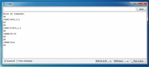
While adding a bluetooth module to Otto is relatively easy, there is be a bit of configuring the HC-05 module. The bluetooth module talks to the arduino over the serial TX and RX pins so we need to configure the module to use the correct baud rate. We can see in the Otto_v3.ino code around line 158 that that speed is 57600, so that’s what we need to set the module to. Also we will be changing the module name from the default “HC-05” name to “Zowi” so the app recognized the module.
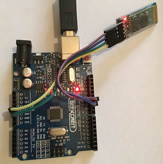
To update the module I followed this instructable and used a spare arduino uno I had lying around to talk to the module. You could use the nano that is inside Otto to do this as they are the same but it was much easier this way.
The write up linked above states the need to hold the key pin high when powering on to get the device into AT mode. I found that all I had to do was to hold the button on the bluetooth module while plugging in the Arduino’s usb lead. If the light on the module starts slowly flashing in 2 sec intervals then you are in AT mode. You can double check this by typing “AT” in the serial monitor of the arduino program and you will get an OK responded back. Once I got the OK back I changed the baud rate by typing “AT+UART=57600,1,0” and the name by typing “AT+NAME=Zowi”. Everything else was left as default, you can check the current settings by typing AT+NAME” or “AT+UART” or “AT+PSWD”. The default password is 1234 which is what is required by the Zowi app.
Once configured you can add the module to Otto, but remember you wont be able to upload the arduino code to him while its connected, so go ahead and upload the Otto_v3.ino code first. Make sure you include the librarys inside your computers “C:\Program Files (x86)\Arduino\libraries” folder too or otherwise it may not compile properly.
To add the module connect RX to D1, TX to D0, VCC to V and GND To G as shown in this diagram here.
When you start the app and connect to Otto the app may complain about wanting to update Zowi code. you can close this warning off and Otto will work just fine with the Zowi app.
If you got this far you should be able to stuff Otto’s new boards inside his tummy and play with his new modes. Be careful when putting him back together that you don’t knock any other wires out or short something. I covered his new boards with electrical tape to avoid any shorts. Now that I have got him doing a few more tricks I think I will add a led matrix mouth to provide visual feedback as well as a Lipo battery to provide more room in his case. These upgrades will be a part 2 blog post in the future.